One of the (much hyped) new features of AutoCAD 2011 was the inclusion of handling pointcloud data. In this post we will take a quick look at this functionality and how you can make real use of this.
The first issue is that AutoCAD can only read specific (limited) pointcloud formats; LAS, XYB and the 2 Faro formats FLS and FWS. Many users will find this a limitation and need further formats. Further formats may be imported by adding the free version of PointCloud from kubit. The product page is here and the software may be downloadedhere. PointCloud adds the formats PTZ, RiScan Pro and ASCII (CSV, TXT etc).
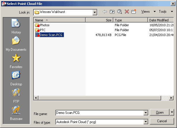
The workflow of importing pointcloud data is to first index the supplied file to create a PCG file which is Autodesk’s pointcloud format.
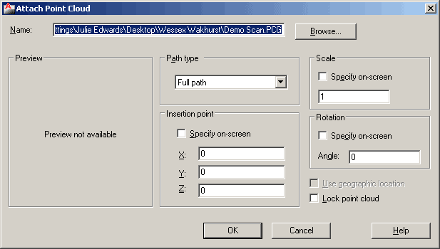
 This PCG file may be attached in the same way as any other AutoCAD block or image file.
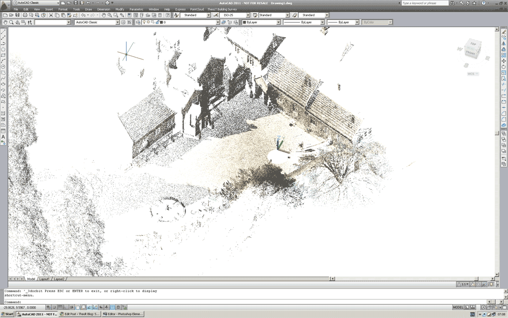
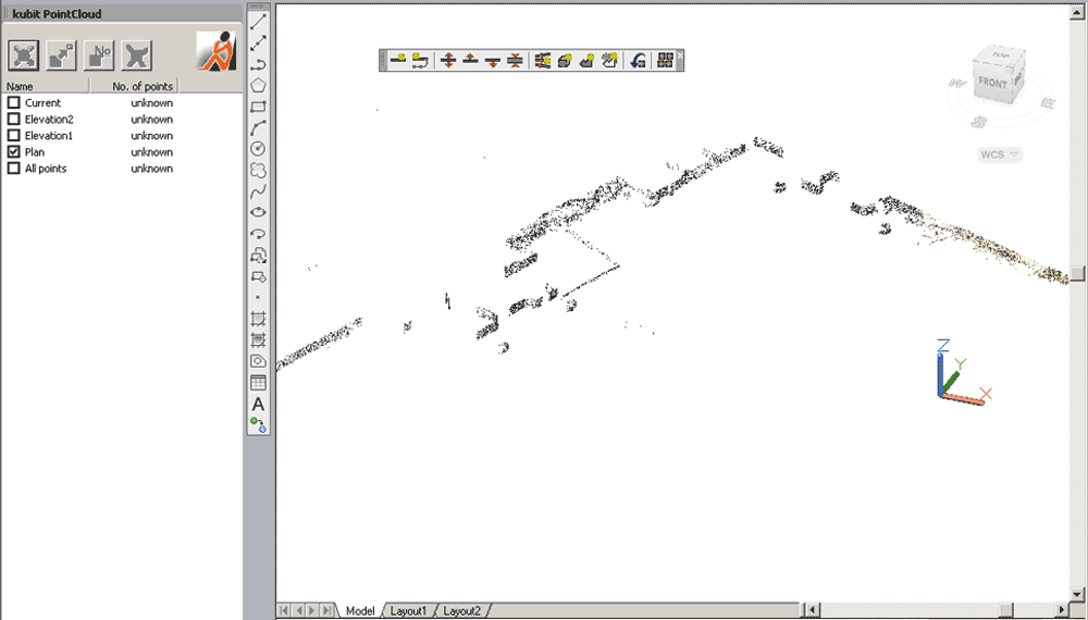
The method of display of the points depends on the current AutoCAD Visual Style. A 2D non-rendered (2D) style displays all of the points in a single colour: black. Selecting a rendered (shaded / 3D) style displays the points in colour.
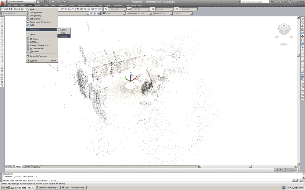
AutoCAD manages the number of points displayed on the screen. At first loading the density of the points displayed may appear rather thin. Select the density command. Here I have set the value 70. The display is now far more usable. You will find the pan and orbit are very quick and all points within the cloud may be via the Node object snap.
Many will view the fact that AutoCAD can only display the whole cloud or no cloud as a major limitation, this is another limitation that may be bypassed with kubit’s PointCloud software although this further functionality requires the paid version.
PointCloud allows the definition of sections which may be managed in the section manager. These may be created in the following ways;
- Slice
- (Shift slice up/down and change slice thickness)
- (Multiple slices: Parallel or perpendicular to objects/curves)
- Clipping Box
- Clipping Polygon (2D projection, inside or outside remains visible).
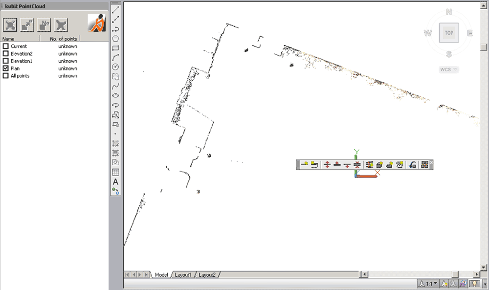
A typical use of the slice command is to create a plan.
This of course may then be traced. If the version of PointCloud being used is the Pro version then the Automatic Fitting may be used to fit the plan to the slice. This is completed by drawing a very approximate polyline (with the correct number of corners) and selecting the Fit Polygon command.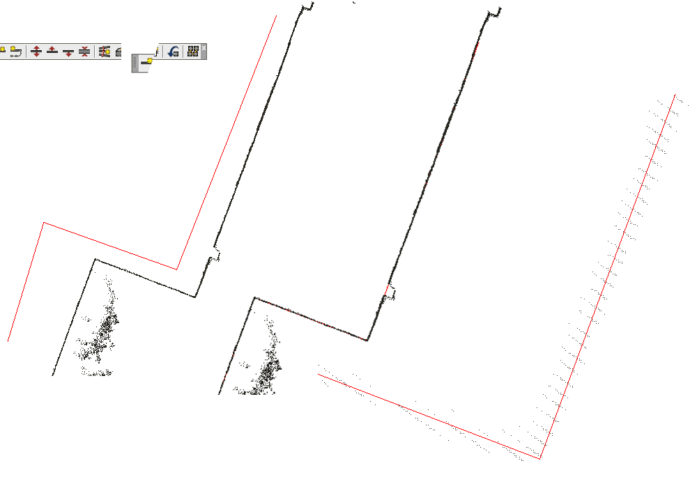
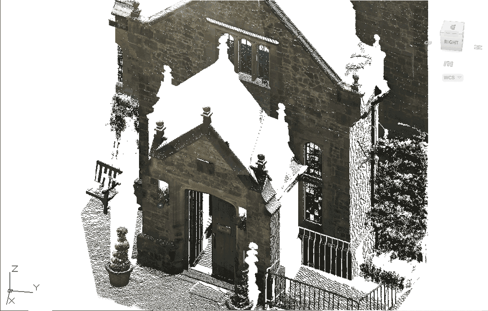
Working with elevations is a key use of PointCloud data. This however shows another weakness in the AutoCAD pointcloud display. The density of the data displayed may not be sufficient for tracing details.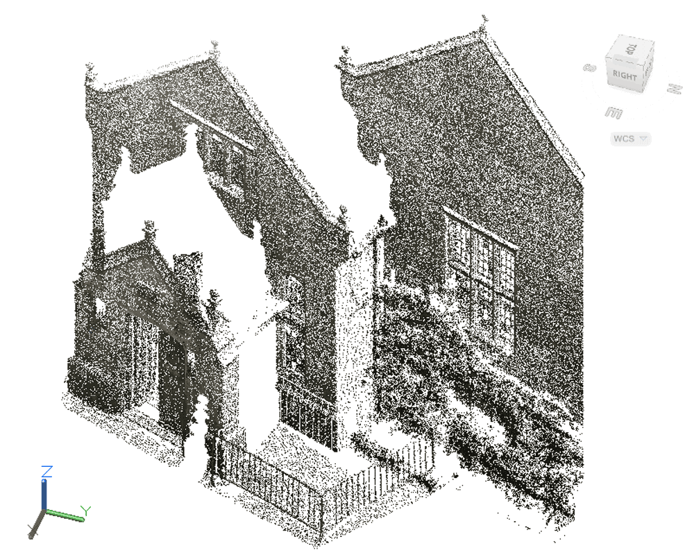
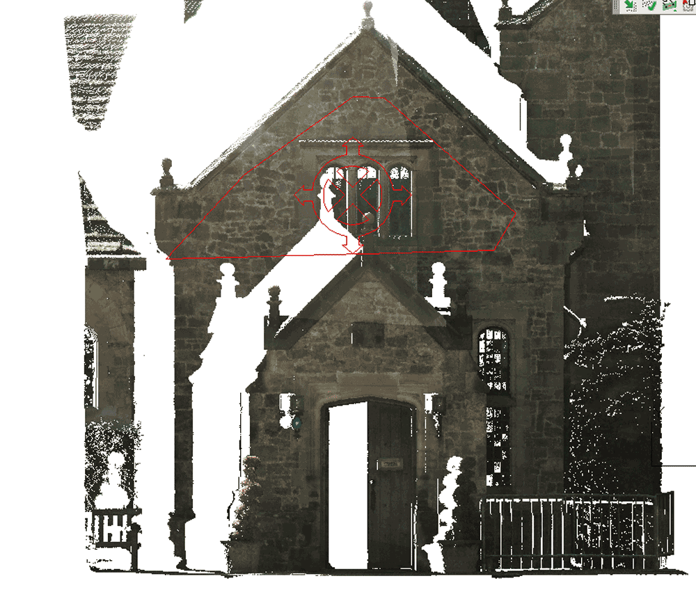
Again, PointCloud may come to the rescue here. Using the section manager individual sections of the data set may be saved in PTC format – the native format of kubit’s PointCloud (which enables the support for PointCloud data in AutoCAD’s prior to 2011). The display of the PTC is far denser allowing the details to be seen clearly.
Edit/Note: Release 7, released in May 2011 introduced “SmartSections” a new way of creating and working with this higher density display. The new SmartSections are faster and simpler to use. End Edit/Note.
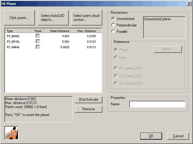
A further tool within PointCloud is Plane fitting. This enables a plane to be fitted to a number of points and in the case of elevations, the UCS placed on this plane ensuring the elevation is drawn in the correct position.
 At first glance it may seem that are are too many disadvantages to using the Autodesk PCG engine and other tools provide a better solution. However when you consider that the PCG engine allows up to 2 billlion points to be inserted into AutoCAD I would suggest that PCG + PointCloud is the ideal tool to manage the dataset within AutoCAD, creating overall plans and views. with sectioning the data to PTC sections for detail extraction. Take time to download and evaluate PointCloud, again details here.
